How To Use An Oscilloscope To Measure Current (in 2024)
How to Measure Current With An Oscilloscope?
Looking to find out how to use an oscilloscope to measure current? You are at the right place!
Measuring current is a straightforward process: connect a multimeter to the circuit you wish to measure, and the meter will provide you with a clean result to work with. When you want to measure shifting signals, things get a little trickier.
Table could not be displayed.Don’t forget to also peruse our oscilloscopes, spectrum analyzers, and other electronics lab tools.
We can use an oscilloscope to see how the voltage between two spots changes over time. You may visually represent your signal by graphing this voltage against time. The majority of oscilloscopes only detect voltage, not current. Nevertheless, there are a few techniques to measure current with an oscilloscope.

Using A Shunt Resistor (Method 1)
The entire understanding instructs us that the voltage across such a resistor is straightforwardly corresponding to the current through it; subsequently, this is potentially the most straightforward strategy to gauge current. Ohm’s law might be summed up as keeps: V = IR, Where V indicates the voltage across the resistor, ‘I’ is the current through the resistor, and R signifies the resistor’s opposition, all in ohms.
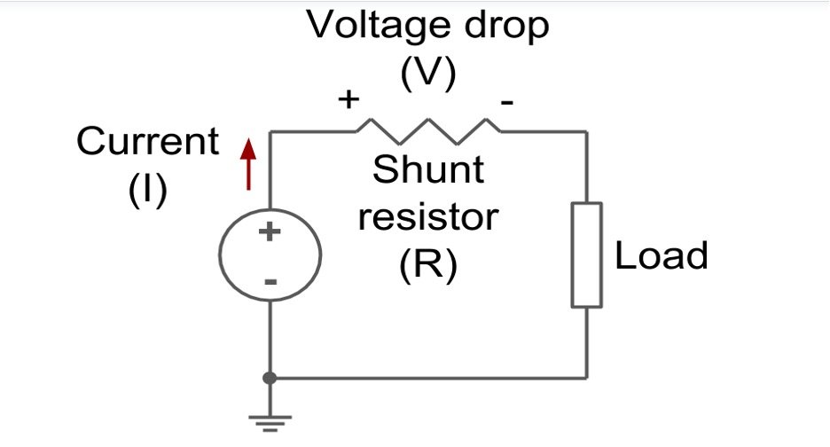
Figure 1: Shunt resistor circuit
Because the voltage drops from across the shunt resistor lead to less voltage being reduced across the circuit it is positioned in; the secret is to pick a resistor value; it does not affect the total circuit being monitored.
To avoid the current in the circuit being measured from being impacted by the shunt, choose a significantly lower resistor than the resistance of the circuit (ten times less is a good starting point).
For example, if the transformer, as well as MOSFET in a DC-DC converter, have such an overall (DC) resistance of hundreds of milliohms, using a large (say) 1-ohm resistor would result in the majority of the voltage getting dropped from across the shunt (recall that the proportion of voltage chose to drop across the resistors is the extent of their protections), resulting in a higher power loss.
The power accomplishes no beneficial work since the resistor turns the current into a voltage for measurement. A modest resistor (1m ohm) would drop a little (but detectable) voltage across it simultaneously, leaving the voltage balance to accomplish meaningful work.
This is the most efficient technique if a current sensing resistor (also known as a “shunt” resistor) is included in the power supply. As long as the overall output is within the probe’s designated working range and the potential difference is significant enough, monitoring the voltage drop throughout the sensing resistor with an actively differential probe will yield satisfactory results.

Using differential probing on low-level signals, on the other hand, requires some consideration of noise removal in the measuring apparatus.
To diminish estimation framework commotion, utilize the most minimal achievable test weakening and limit recurrence on the test or oscilloscope. Remember that the test’s capacitance and opposition will, in any case, be in correspondence with the detecting resistor. While this is intended to reduce the influence of the system under test, you should be aware of it.
Putting sensing resistors in series connections demand meticulous planning. According to Ohm’s Law, when the resistance value goes up, the voltage drops each ampere increases, enhancing the accuracy of the current sensor. However, because the resistor’s power dissipation rises with the square of both current, the excessive voltage drop should be factored in.
Resistors also provide inductance to the circuit. Recollect that the split test input capacitance is in series with the detecting resistor, delivering an RC channel.
Assuming you should remember a detecting resistor for the circuit, place it as near unbiased as possible to lessen the normal mode flags that the estimation arrangement should dismiss. Furthermore, despite high-performance current probes, differential voltage measurements’ common-mode rejection ability tends to decline with frequency, lowering the reliability of high-frequency measured data using sense resistors.
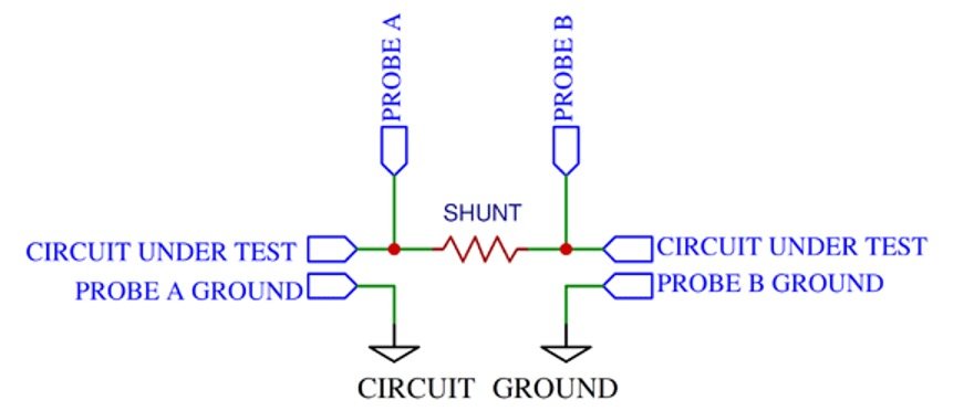
Figure 2: Differential Voltage Measurement
Disadvantages Of Using A Shunt Resistor
- Using a shunt resistor has a few drawbacks. The first is the level of tolerance, which can be as low as 5%. It’s something that will take some time to account for.
- The temperature coefficient is the second. Temperature causes resistor resistance to rising, resulting in a higher power loss for such a given current. This is particularly risky when utilizing high-current shunt resistors.
Using Current Probe (Method 2)
Although fully prepared current probes (also known as “current clamps”) are commercially available, amateurs do not often use them due to their cost.
These probes work in one of two ways. A coil twisted around with a semi-circular ferromagnetic material is the first way. The current in the wire around which the probe is clamped creates a magnetic in the ferrite. This produces a voltage in the coil. The speed of advancement of current is relative to the likely distinction.
The waveform is ‘integrated’ by an integrator, which generates an output proportionate to the current. Typically, the output range is between 1mV and 1V for each amp. In the second technique, a Hall sensor is placed between the two ferrite semicircles. The current is relative to the applied voltage delivered by the Hall sensor.
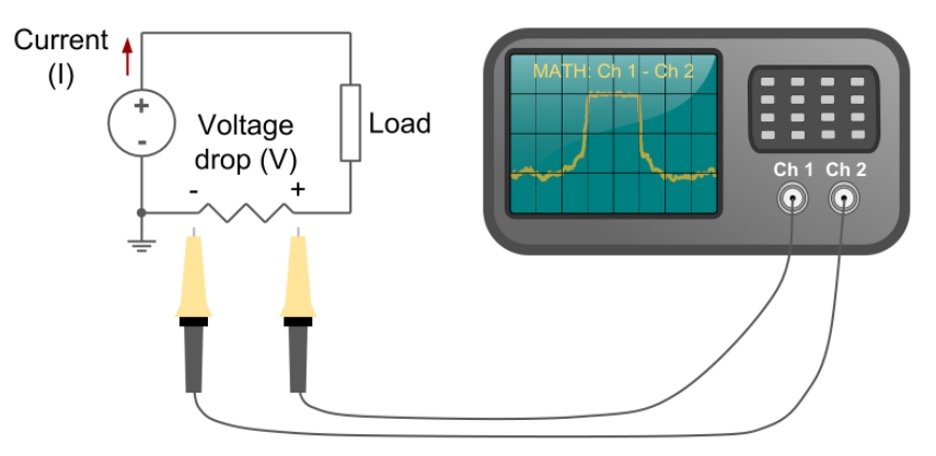
Figure 3: Differential probe setup
Current Probes In Oscilloscopes
Current probes in oscilloscopes are partitioned into two classifications:
- Probes for detecting AC current
- Current probes (AC/DC)
The two variants utilize the transformer activity idea to identify exchanging current (AC) in a guide. Substituting current should pass across a guide for transformer activity to happen.
As indicated by the greatness and bearing of the current stream, an AC current causes a motion field to develop and implode.
When a sensor loop is embedded in this attraction, basic transformer activity makes a proportional voltage across the coil.
This amperes voltage signal is then separated and displayed as a current-scaled waveform on an oscilloscope.
The most basic AC current probes include passive components that consist of a coil coiled to exact parameters on a ferromagnetic material made of ferrite.
Some are strong toroid’s, requiring the guide to be steered through the center by the client. Split-center current tests depend on a very much designed mechanical construction that permits its center to be broadened and cinched around the wire without upsetting the test circuit.
Split-core current probes offer excellent sensitivity and can work without electricity, but they are mechanically inflexible and have a narrow aperture, limiting their usefulness.
Reviewer Final Comments
We hope after reading this article, you have learned how to use an oscilloscope to measure current. These methods provide valuable options for engineers and technicians seeking to accurately measure current.
The choice between the two methods depends on factors such as the level of precision required, the nature of the circuit, and any potential limitations or sensitivities that need to be considered. Both methods help users gain insights into current behavior, enabling them to make informed decisions and ensure optimal performance in their electronic systems.